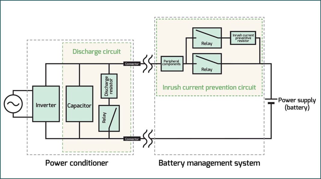
The vast majority of power converters used in the EV space—from battery chargers to traction inverters—are classified as voltage-fed, meaning they expect to be supplied from a source whose voltage varies little with changes in current draw (i.e. has a low impedance), and the best way to ensure this condition is with a capacitor across the power input, as it will effectively nullify any upstream stray inductance in the wiring, etc.
The amount of input capacitance required tends to scale directly with current draw or power level, and inversely with pulse frequency or voltage, but once you get to the kW power level and/or above 48 V, you can pretty much guarantee that directly connecting power without some means of controlling the ensuing inrush current will end in tears, as dividing a high supply voltage by a low loop impedance (including the capacitor Equivalent Series Resistance, or ESR) can easily result in tens of kiloamperes of inrush.
There is an easy solution to the problem—well, easy in theory, anyway—and that is to bring the capacitor voltage up slowly, a process typically referred to as precharging. The sophistication (read: complexity and cost) of these precharging (and inrush current control measures in general) also tends to go up with supply voltage and power level, though complicating factors like safety agency requirements will often severely constrain what approaches will be acceptable, regardless of how effective they might be.
Low-power auxiliary converters supplied by moderately high voltages (drawing a continuous current of fusible resistor). While this might sound like anathema from an efficiency standpoint, the absolute losses we are talking about here should be less (much less, really) than 1 W. For example, a 100 Ω resistor in series with a 340 V supply will limit inrush current to a downstream converter to a maximum of 3.4 A, and if the converter only has to supply a load of 5 W at an efficiency (sans resistor) of 65%, then it will draw about 23 mA, incurring an additional loss in the series resistor of around 50 mW. That’s a minuscule increase in loss by any standard, but do keep in mind that this loss will scale with the square of converter power, and once it reaches about 1 W, the size of the resistor required to keep its surface temperature reasonable (i.e. well below 100° C) starts to get ridiculous.
SEE ALSO: A closer look at the DC Link
Another inrush current-limiting solution that is just as simple as a fixed resistor is one with a negative temperature coefficient. Such NTC inrush current limiters are resistors that will typically swing from 5 Ω to 50 Ω at 25° C down to 1/10th to as little as 1/50th of that value when heated (by the current flowing through them) to around 100-200° C. This 10x to 50x reduction in continuous losses without any penalty in inrush current limiting makes a compelling case for the NTC resistor, but one major downside for EV applications—especially for onboard devices—is that the allowable ambient temperature range is necessarily limited.
A less-appreciated caveat is that a properly spec’ed NTC inrush current limiter will necessarily get quite hot during operation, and there is no option to oversize it to reduce said operating temperature, as is possible with a fixed resistor. Another possible downside is that the NTC resistor will need some time to cool off when the load is removed before it will once again limit inrush current (1-2 minutes is typical), so loads that are cycled often (or which vary considerably) aren’t a good fit.
The precharge resistor can be tricky to properly specify, as it needs to be of a construction that is capable of handling a very high peak power.
The next approach for controlling inrush current is with a fixed resistor that is switched in to bypass the main contactor before the latter is closed. The trigger conditions for the precharge switch can be as simple as a fixed time delay (though this is really not recommended), or something more elaborate, such as when the capacitor voltage comes up to within a few volts of the incoming supply, or the current through the precharge resistor drops below a certain value. The precharge resistor can be tricky to properly specify, however, as it needs to be of a construction that is capable of handling a very high peak power (namely, W = VIN2 / R), even though the average power may be quite low, depending on the time between power cycles (according to the equation W = C * VIN2 / 2 * seconds).
Generally speaking, bulk metal, wirewound and metal oxide resistors are most suitable for precharge use, while the film types—pretty much regardless of construction—tend to die prematurely. Resistors appropriate for precharging applications will often be specified by energy rating in addition to the more usual power rating, with the required energy rating coming from the capacitor energy equation (i.e. J = C * VIN2 / 2). For example, if the incoming supply is 340 VDC and the capacitor is 1,000 μF, then the precharge resistor will need an energy rating of at least 58 J. Sometimes a pulse energy rating in joules isn’t directly specified for a resistor of a preferred construction, but if a short-time overload of, say, x times the rated wattage for y seconds is given, then the energy rating can be extrapolated by simply multiplying x and y.
For example, the Ohmite TWW series (wirewound) are specified for 10x rated power for 5 seconds, so a 5 W resistor in this series could theoretically handle 250 J. That’s the theory, anyway, but my experience is that it’s best to assume the peak power rating is only tolerable for 1-2 seconds, max, and to string several smaller power resistors in series—particularly when VIN exceeds 300 V—to achieve the necessary energy rating. Finally, ensure that the average power rating won’t be exceeded, and be generous with this derating, as well, if for no other reason than to protect nearby components from excessive heat.
The switch in series with the precharge resistor also needs to be chosen carefully, as it must withstand the full supply voltage when open, and will then have to close into the highest current expected once precharging commences. The latter condition is notorious for welding the contacts of an electromechanical relay (an issue that is sidestepped with a solid-state relay). It is also important to consider what might happen to the precharge switch (and the main contactor it bypasses) during a short-circuit fault downstream, as then the voltage on the bus capacitor won’t rise, so either the precharge switch will have to open under its maximum DC current—which will result in arcing in an electromechanical relay—or else the main contactor will be closing into a short (if the precharging sequence is performed blindly).
Standard electromechanical relays intended for AC switching are notoriously poor at breaking even a few tens of mA of DC current—the datasheet will typically show 1/10th the maximum AC rating at a mere 30 VDC—which is yet another argument for the SSR, but regardless, monitoring the bus capacitor’s voltage and aborting precharge if it doesn’t rise to the expected value within the expected time (+/- whatever tolerance is appropriate for the variation in capacitance value as well as that of the incoming supply voltage) is still highly recommended. Such monitoring also allows for closing the main contactor when there is an ideal 5-10 V still to go, as this will ensure that enough current flows during closure to blast oxides off its contacts, but not so much that they weld.
Finally, there is active precharging, which effectively replaces the resistor in the passive methods discussed above with a current source.
Also note that electromagnetic relays don’t tolerate high shock loads/vibration without some effort going into hardening them against such, which puts them at a further disadvantage against SSRs when used onboard an EV. That said, they are typically a lot cheaper than their solid-state counterparts, and they possess one advantage that is rarely (pretty much never) found in an SSR, which is a true Form C contact arrangement—that is, dual-throw, or a common pole switching between normally closed and normally open positions—which makes it very easy for the precharge resistor to turn around and discharge the bus capacitance. Not that there isn’t a semiconductor-based solution to rapidly discharging the bus capacitance, just that a SPDT relay can do such for (almost) free.
Finally, there is active precharging, which effectively replaces the resistor in the passive methods discussed above with a current source. This can dramatically reduce the peak power that must be handled without a corresponding increase in the precharging time, as the current source will cause the capacitor voltage to rise linearly over time, rather than in an exponentially decreasing fashion. This comes at the expense of increased complexity, if not total cost itself, hence active precharging methods are best reserved for applications which have a large value bus capacitance that needs to be precharged rapidly (e.g. the traction inverter in an EV).
The current source for active precharging can be a fairly simple linear type comprised of bipolar junction transistors or depletion-mode FETs, but note that this really just shifts the burden of dissipating power during precharging from a physically robust resistor to a comparatively more fragile transistor. These losses can be eliminated by using a standalone switchmode converter that is configured as a current source to do the active precharging. While almost any switchmode converter can be made into a current source via its control loop, some topologies are more suitable for this job than others. For example, the classic ringing choke converter (aka blocking oscillator or self-oscillating flyback) was very commonly used to charge the energy storage capacitor in battery-powered xenon photoflash strobes (and was responsible for their distinctive rising-pitch whine), which is pretty much what is required here.
Another good topology choice for active precharging is the buck converter, with the capacitor to be precharged substituting for its output capacitor.
The RCC topology automatically limits output voltage and current even without a formal control loop, which is a big plus, but one major downside is that its switch must withstand more than twice the input voltage (assuming a 1:1 transformer turns ratio), which means a lot of board space will be needed just to accommodate the creepage and clearance requirements around it, if nothing else.
Another good topology choice for active precharging is the buck converter, with the capacitor to be precharged substituting for its output capacitor. A control loop will be needed to limit and/or regulate the output current with the buck, but the switch (and freewheeling diode) never see more than the input voltage, and the buck choke only needs a single winding, rather than at least three windings, as is required for the RCC. That said, the buck will require a low-voltage power rail for its control circuit and some means of driving its (usually high-side) switch, meaning a gate driver IC that is either of the level-shifting type (overall less robust and limited in the range of duty cycle it can handle) or which provides isolation (somewhat more expensive).
For those interested in further reading on active precharging, Texas Instruments’ design guide, TIDA-050063, describes several approaches, including a buck converter-based solution for precharging a capacitance of 2,000 μF up to 800 VDC in 400 ms—something which would almost certainly be cost- and space-prohibitive if attempted with a resistor and a relay!
Read more EV Tech Explained articles.
This article first appeared in Issue 73: July-September 2025 – Subscribe now.


