As electric vehicles push toward more efficient and higher voltage architectures, the limitations of traditional fuse and contactor protection are becoming harder to ignore. False triggering, single‑use hardware, and complex redundancy add cost, weight, and downtime. This webinar addresses these challenges head‑on and introduces an innovative approach for high voltage fault management.
Join the webinar at next week’s Virtual Conference on EV Engineering, presented by Sensata Technologies, where we will walk through the engineering principles behind passive and active fault clearing and show how resettable protection can minimize nuisance trips, improve serviceability, and simplify system integration.
Drawing on validation data up to 16 kA at 1 kV, we will compare conventional contactor plus fuse and pyrofuse designs to a new approach that combines these functions into a single package, evaluating each for safety, thermal performance, cost, and complexity. Attendees will leave with a practical framework for specifying robust, adaptable electrical protection that reduces component count, lowers thermal losses, and supports next‑generation EV architectures.
Key takeaways:
Discover how innovative, resettable protection strategies can reduce system cost, weight, and complexity while enhancing safety.
Gain data-driven perspectives on managing high magnitude fault currents and minimizing downtime in next-generation EV architectures.
Learn how collaborative approaches and system-level thinking are driving the industry toward more robust and adaptable electrical protection solutions.
Broadcast live from March 9 to 12, 2026, the conference content will encompass the entire EV engineering supply chain and ecosystem, including motor and power electronics design and manufacturing, cell development, battery systems, testing, powertrains, thermal management, circuit protection, wire and cable, EMI/EMC and more.
Pretty much every product, device or subsystem involved in power conversion, both on- and off-board anw EV, will have to comply with both safety and ElectroMagnetic Compatibility (EMC) regulations.
And while most power electronics engineers find the safety regulations to be relatively straightforward, I’d wager that few feel the same about the EMC ones. EMC compliance is not entirely a dark art, however—a good understanding of the basic physics involved will allow one to sidestep most EMC issues in the design phase, and for the rest there are plenty of purveyors of noise filtering components that are very effective (so long as one is not trying to slap a proverbial bandage on an arterial wound).
Regardless of the specific set of EMC regulations that might be enforced on a given device or product, compliance with them will generally consist of four components: minimizing the emission of, and maximizing the immunity to, both conducted and radiated noise over a specified frequency range (e.g. 150 kHz to 2.5 GHz).
Compliance with EMC regulations will generally consist of four components: minimizing the emission of, and maximizing the immunity to, both conducted and radiated noise over a specified frequency range.
Radiation is the dominant route for EMI into or out of a device at higher frequencies, because wiring length and enclosure openings will be more likely to approach half a wavelength (where wavelength, λ, in meters = 300 / f in MHz), which happens to make for a very efficient antenna. Conversely, the attenuation caused by the various stray series inductances and shunt capacitances in wiring, PCB traces, etc, will decline with frequency, hence the conduction of EMI prevails at the low end of the range. While there isn’t a hard line of demarcation in frequency between the two mechanisms in reality, most EMC testing standards worry about conduction below 30 MHz and radiation above it.
Since the cost of formal EMC compliance testing typically runs into the kilodollars/hr range, it is well worth the effort to find and address noise problems before scheduling time at the testing facility. Fortunately, a surprising amount of troubleshooting can be done at modest cost with a set of near-field EMC probes and a spectrum analyzer (ideally one with a built-in tracking generator).
Since the cost of formal EMC compliance testing typically runs into the kilodollars/hr range, it is well worth the effort to find and address noise problems before scheduling time at the testing facility.
Near-field probes are actually much better suited to pinpointing radiated emissions and immunity problems than the antenna-based setup that will be used in the formal tests, and they can also tell you whether such problems are the result of RF currents or voltages (that is, H- or E-field, respectively).
H-field probes can also be used to ferret out immunity problems by driving them with an external RF source (such as a spectrum analyzer’s tracking generator) to subject PCB traces, wiring and even enclosure openings to relatively high field strength levels with just a few mW of power, versus the several W of power needed if driving an antenna in the far field (though to be fair, the latter is how the certified test lab will do immunity testing, so this is a bit of an apples/oranges situation).
Evaluating conducted emissions and immunity requires a specialized filter to decouple the power supply from the Device Under Test (DUT), typically referred to as a Line Impedance Stabilization Network (LISN), and while you can certainly make such yourself, these filters are also commercially available at reasonable cost. Conducted emissions are measured with a spectrum analyzer by passing one or more power or signal wires to the DUT through a wideband current transformer that is specified for EMC testing. Conducted immunity is tested by injecting RF current into one or more wires to the DUT via an inductive (or, less commonly, capacitive) coupler, otherwise known as Bulk Current Injection (BCI).
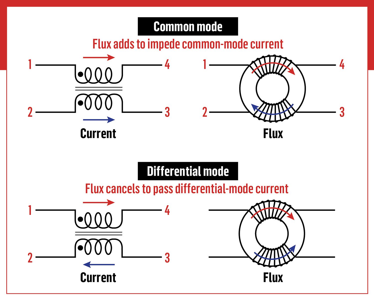
Most noise problems are the result of common-mode voltages or currents (that is, of similar amplitude and in phase on all wires), but differential mode noise can be measured or injected by reversing the direction of either the forward or return wire as it passes through the current transformer or BCI, respectively (in which case the measured/injected value should be reduced by 3 dB). For those interested in (or in desperate need of) more information, I highly recommend a 3-part book series on EMC by Kenneth Wyatt as well as EMC for Product Designers by Tim Williams. Two smaller YouTube channels that are particularly helpful are Hans Rosenberg and Dr. EMC.
Most noise problems are the result of common mode voltages or currents—that is, of similar amplitude and in phase on all wires.
Avoiding EMC emissions and immunity problems through judicious design is far better than troubleshooting and then ameliorating them, and a high-level design decision that can really pay off here is to go with a “soft-switching” (aka quasi-resonant) or a fully resonant converter topology. While these converters can be trickier to get working, they will usually exhibit much less ringing at the switching transitions, which would otherwise be a major cause of EMC testing failure, and they’re often more efficient to boot.
Moving on to the board level, making one of the inner layers of a multilayer board a solid ground/return plane is the closest thing there is to the proverbial silver bullet. A solid ground plane in close proximity to signal/power traces cancels out almost all of the H-field that might otherwise radiate from (or impinge upon) them, both reducing noise emissions and susceptibility to such, with the bonus effect of lowering trace inductance.
A corollary to this rule is to not split or otherwise interrupt this ground plane except for galvanic isolation reasons. This runs counter to the advice from yesteryear that ground planes between noisy power or digital circuits and quiet analog ones should be split, with only a single jumper or trace connecting them, but unless you can be absolutely sure that no high-frequency signals/currents will have to traverse that trace, it’s best to just use one big ground plane for everything (again, except for galvanic isolation). Galvanically isolated ground planes can be quieted by providing a return path for high-frequency common-mode currents through one or more Y capacitors (i.e. safety agency-rated for line-to-earth use) that tie back to the main (earthed) ground plane.
Another helpful tip is to always use some kind of termination on traces or wires carrying high-speed digital signals—either a series resistor at the sending end or “split termination” at the receiving end (or to enable pin-level termination, as is usually an option with FPGAs and most DSPs). Finally, be very wary of capacitively coupling high dV/dt from the drain tab of any switch operating at high frequency and voltage to the outside world. Clamping a GaN HEMT that is switching > 300 V at 1 MHz onto the inside of an aluminum enclosure to use the latter as a heat sink may very well turn said enclosure into the E-field radiator of the year.
At the wiring level, any board-to-board interconnects inside a device with a high-power switchmode converter—which is pretty much every major device related to EVs—should either use differential signaling or else pair up every singled-ended signal wire with a return wire. Ribbon cable makes either option exceptionally easy, and it is even available with twisted-pair construction, which is yet another way to minimize EMC problems (though differential signaling is needed to get the most out of twisted-pair). Cable shielding can be very effective at blocking EMI, but it can also be a major source of such.
The two main rules here are that the shield should be treated as if it were part of the enclosure, and not a return path for high-frequency current, and that the shield should be bonded over its full circumference at the enclosure ends, and not through a soldered pigtail. Then there is the classic panacea for minimizing wiring EMC problem: the clip-on (or molded-on) common-mode choke (CMC) made of a lossy ferrite material. While the “it can’t hurt” philosophy more or less applies here, a CMC works best on wires/cables that are operating at a low impedance, particularly if emissions are the main concern (conducted or radiated).
Also note that the impedance of a half-wave antenna is lowest at the ends, hence the CMC should be placed there on a cable, rather than somewhere in the middle. Similarly, AC or DC power inputs and DC outputs will almost certainly need a common-mode filter of some type, and note that the AC mains type will also need safety agency certification, so this is definitely a case in which going with an off-the-shelf product makes the most sense.
At the device/enclosure level, the most maddening (and often unavoidable) cause of EMC problems are slots, holes and poorly bonded seams in the enclosure. In this regard, rectangular openings (including poorly bonded seams) make for better antennas than round holes, but in all cases the usual thumb rule is to keep the longest dimension of any opening in the enclosure below λ / 20, though λ / 50 is ideal, relative to the highest frequency found (or expected) to be an issue. This thumb rule seems eminently reasonable at face value, as that would mean that no opening should exceed 24 cm (~9.5 in) if the highest frequency inside a device is a 25 MHz clock, for one common example. If 2.4 GHz cellular/WiFi signals turn out to be a problem, however, then the maximum permissible opening is now a mere 6.25 mm (~0.25 in)!
The issue of poorly bonded seams (e.g. between enclosure and lid) is especially common with aluminum due to the inevitable oxide layer that is present—whether this oxide layer is formed naturally from atmospheric oxygen, or intentionally from anodizing—but careless painting/powder coating, or simply relying on too few fasteners to assemble the enclosure, can cause the same problems with any metal. One very effective, albeit pricey, solution is to use a metal mesh gasket (like an O-ring made out of steel wool) between any seams, but if all else fails, then nickel plating aluminum will guarantee good contact even without a ridiculous number of fasteners (or pricey metal gasketing).
The last resort for reducing EMC problems is metal shielding, as it tends to be rather costly from an assembly labor standpoint, but there are times when it will be difficult to avoid.
The last resort for reducing EMC problems is metal shielding, as it tends to be rather costly from an assembly labor standpoint, but there are times when it will be difficult to avoid. For example, an LCD display is likely to require an opening in the enclosure that lets out (or in) too much EMI, and if the display can’t be moved to a quieter (or more immune) location, then a metal shield may very well be the only effective solution. The good news is that even very thin shielding will reliably block high-frequency E- or EM-fields as long as it is highly conductive and solidly bonded to ground (read: with minimal inductance). For H-fields, the shielding mechanism shifts from being dependent more on material permeability at low frequencies to the induction of eddy currents as frequency goes up, but in all cases the amount of attenuation afforded by shielding will be proportional to the thickness of the shield itself.
The same guidelines as for traces/wiring apply here, but some of the biggest H-field offenders are E-core magnetic components with a discrete gap (especially if the gap extends across the legs). Besides confining the gap to the center post only, another effective solution is a “flux band,” which is a metal shield consisting of a single wrap of copper foil that encloses the coil former and legs. Note that any metal shield (including a flux band) needs to be solidly bonded to the enclosure or PCB ground plane, just as with cable shields, to provide a return path for any induced noise currents—failing to do so will turn the shield into an antenna, which is the exact opposite of what you want!
Port facilities represent a grove of low-hanging fruit when it comes to emissions reduction—ports are potent sources of local air pollution, but many classes of equipment and vehicles used in and around ports (including, as regular Charged readers know, terminal tractors) present near-ideal use cases for EVs.
Port electrification can also deliver substantial economic benefits, as detailed in a new report.
Florida is home to 16 seaports, including the world’s 3 busiest cruise ports. Collectively, Florida’s ports contribute over $117 billion per year to the state’s economy, and represent about 13 percent of the state’s GDP.
The study found that, while some electric cargo-handling equipment carries higher upfront costs, lower fuel and maintenance expenses can result in meaningful long-term savings. For example, electric rubber-tired gantry cranes (eRTGs) cost about 30 percent more than legacy diesel models but deliver average annual savings of more than $60,000 per unit over a 20-year lifespan. Electrified equipment also enables ports to stack cargo higher and use limited space more efficiently.
Shore power infrastructure allows ships to plug into the electrical grid while docked, reducing fuel use and improving local air quality. Seven Florida ports have already installed shore power, or have projects underway. Some 72 percent of cruise ships are anticipated to be shore power-capable by 2028.
“Modernizing equipment and infrastructure helps ports attract customers, improve efficiency, and reduce long-term operating costs,” said Rohemir Ramirez Ballagas, Director of Shipping and Transport at EDF. “This report demonstrates that leadership in electrification delivers clear business advantages.”
“EDF’s report on electrification at Florida’s ports highlights the significant benefits—ranging from improved efficiency to modernization—of technologies like shore power and electric cargo-handling equipment,” said John Bressler, VP of Government Relations for the American Association of Port Authorities (AAPA). “AAPA was pleased to help support its development, and we look forward to seeing the state’s maritime industry continue adopting cutting-edge technology, while also strengthening supply chain reliability.”
“To remain competitive with other major cargo ports along the Eastern Seaboard, Florida ports must increasingly focus on terminal optimization and densification to expand capacity and improve throughput,” says AECOM VP Philip Hadfield. “In today’s maritime industry, this evolution is most effectively achieved through the electrification of container yards and cargo-handling equipment.”
China’s updated standards set one of the strictest global EV battery safety standards, requiring testing under extreme conditions. The European market and U.S. manufacturers are expected to follow.
What tools do battery engineers need in order to balance battery performance and safety?
To meet these regulations and help ensure battery thermal safety across all applications, AVL has developed a “No Flame-Out” pack design that leverages simulation, empirical testing, and analytics.
Join this webinar at next week’s Virtual Conference on EV Engineering, presented by AVL, to learn how employing an integrated approach that combines multi-scale simulation, rigorous safety testing, and data-driven analytics enables engineering teams to develop safer, more compliant battery designs more quickly.
Broadcast live from March 9 to 12, 2026, the conference content will encompass the entire EV engineering supply chain and ecosystem, including motor and power electronics design and manufacturing, cell development, battery systems, testing, powertrains, thermal management, circuit protection, wire and cable, EMI/EMC and more.
Vector Informatik has expanded its vCharM charging and energy management system with features aimed at making VDV 261-compliant preconditioning easier to deploy for electric bus fleets. Working with Hubject, Vector says it can now automate the certificate management required for secure VDV 261 communications, and its vCharM.edge hardware can support VDV 261 communication in existing IPv4 networks.
VDV 261 preconditioning lets an e-bus use energy from the charging station to preheat or precool key components before leaving the depot, so the vehicle can start service with more usable battery energy available for driving. The catch is that VDV 261 requires secure TLS connections and (per the standard) IPv6-based communication between the vehicle, charging station and backend—two areas that can turn into real-world deployment headaches.
On the security side, Vector says vCharM now supports automated creation and distribution of the required certificates via a public key infrastructure, reducing the manual work of generating and installing certificates across charging stations and backend systems. On the networking side, Vector says vCharM.edge includes an IPv6-to-IPv4 proxy, allowing VDV 261-compliant communication without requiring operators to overhaul their existing IPv4 infrastructure.
“We are removing two of the biggest practical barriers to implementing VDV 261: complex certificate management and the requirement for IPv6 in typical IPv4 infrastructures,” said Christian Witt, Product Manager at Vector.
Harbinger, a manufacturer of medium-duty EVs (see our recent interview with CEO John Harris), has acquired autonomous driving company Phantom AI. The Phantom AI team of 30 employees will continue to operate in Mountain View, California.
Harbinger will incorporate Phantom AI’s computer vision into its vehicles, enabling ADAS features such as emergency braking, adaptive cruise control, lane keeping and more.
Harbinger and ZF Group’s Advanced Driver Assistance Systems (ADAS) business unit also plan to license Phantom AI’s computer vision for passenger car ADAS products. The acquisition of Phantom AI and the partnership with ZF Group create a new software services revenue stream for Harbinger.
“Our acquisition of Phantom AI and partnership with ZF are pivotal milestones for Harbinger as we expand beyond commercial vehicles and enter new segments for the first time,” said John Harris. “We are combining Phantom AI’s computer vision with ZF’s global reach and leadership in automotive systems to unlock an entirely new revenue stream of software services and autonomy. At the same time, we are incorporating even more advanced driver assistance and safety features into our medium-duty vehicles, which is something our large Fortune 500 customers have been asking for.”
“Licensing Phantom AI’s computer vision will help strengthen ZF’s passenger car ADAS portfolio,” said Christopher Ludwig, VP of Procurement for ZF’s Electronics & ADAS Division. “This collaboration allows ZF to provide a broader selection of products and options to our customers today while creating a path for future autonomous driving capabilities.”
“Thanks to this acquisition, we are able to deliver a more comprehensive, technology-forward solution that includes robust ADAS capabilities and telematics to the medium-duty vehicle segment and beyond,” said Dr. Cho, co-founder and CEO, Phantom AI. “While these features are already expected in passenger vehicles, medium-duty fleets have historically been underserved.”
Beam Global sells a versatile off-grid solar-powered EV charging solution. HEVO provides wireless charging hardware and a supporting software platform. Now the two companies have partnered to launch an integrated autonomous wireless charging system.
The system is aimed at the autonomous vehicle (AV) sector, and is adaptable to a wide range of commercial EV fleet applications in which vehicles need to be charged without human intervention.
The combination integrates HEVO’s Rezonant UL-certified and SAE-qualified wireless charging hardware and Journey software platform with Beam Global’s rapidly-deployable EV ARC charging product. The companies are offering a turnkey charging package that enables fully automated charging without trenching, utility interconnection or manual intervention.
Most AVs currently rely on clumsy human beings to plug them in, making even the most capable AVs reliant on human intervention. The Beam Global/HEVO solution is designed to make AVs fully autonomous and powered entirely by renewable energy.
Beam Global and HEVO are rolling out the system with “select international customers” and will jointly demonstrate autonomous EVs equipped with the new system at sites in the US and the UAE “in the coming months.”
“Beam’s patented wireless charging coupled with HEVO’s technology is a natural and essential combination for AVs,” said Desmond Wheatley, CEO of Beam Global. “We are delivering a market-ready solution that removes the barriers of grid dependency, civil work and manual charging. We are already seeing strong interest from customers around the world, and our upcoming demonstrations will highlight how this integrated platform accelerates commercial adoption.”
“Autonomous fleets are not autonomous if charging is not automated, resilient and immediately deployable,” said Jeremy McCool, founder and CEO of HEVO. “Our patented Rezonant wireless charging hardware and Journey software platform, integrated with Beam Global’s EV ARC systems, deliver exactly that.”
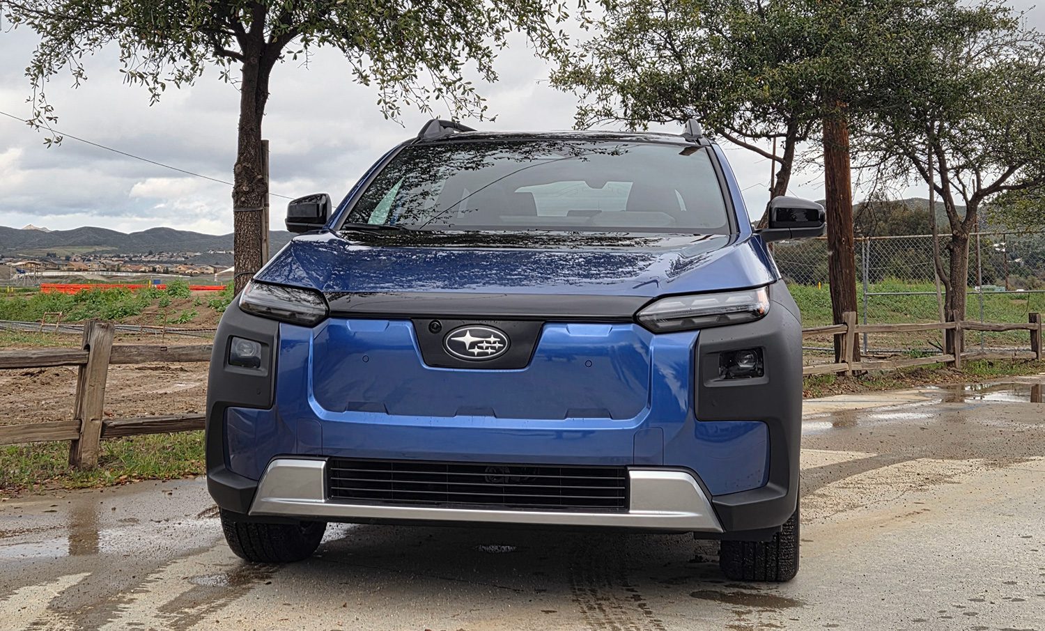
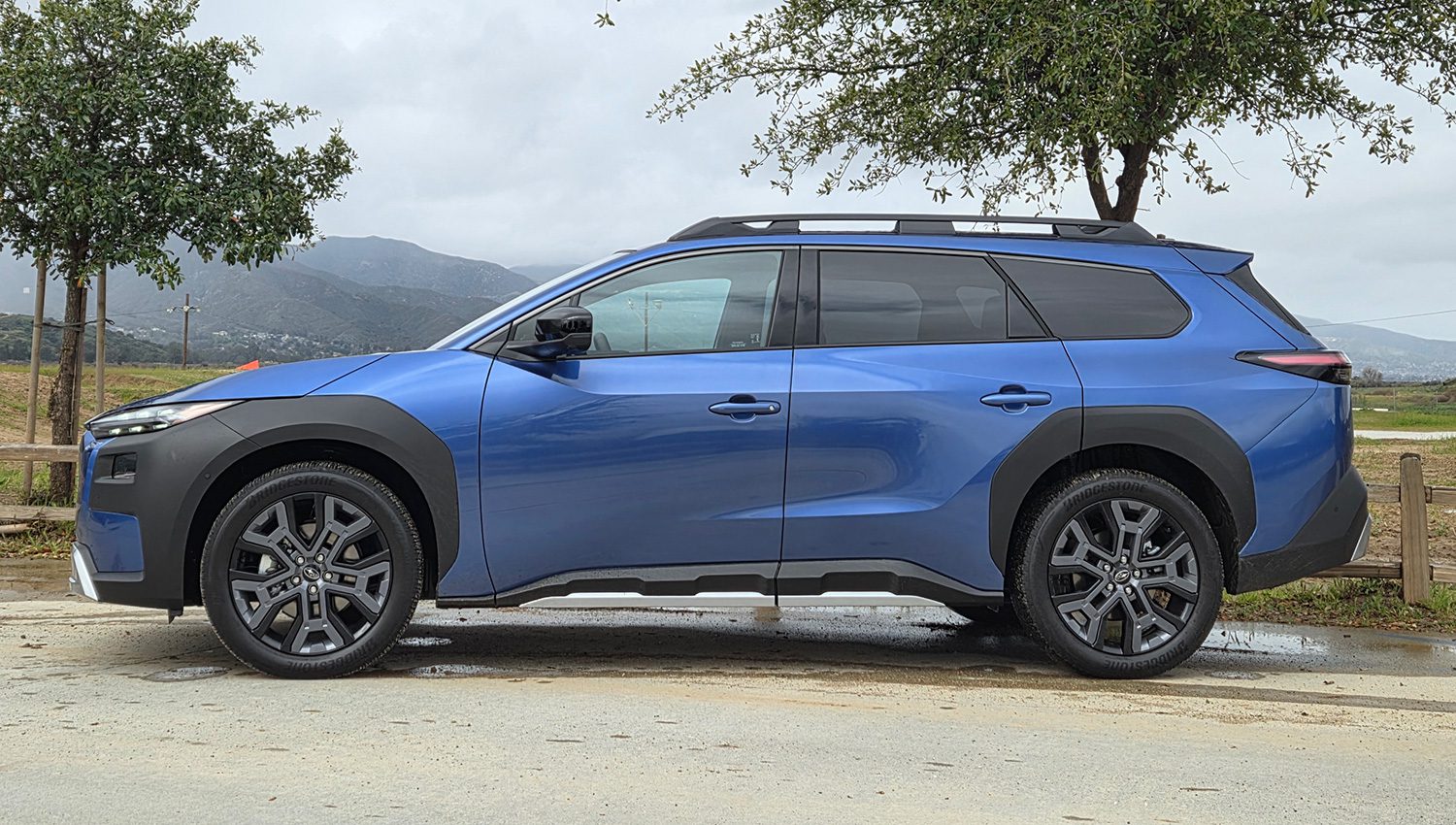
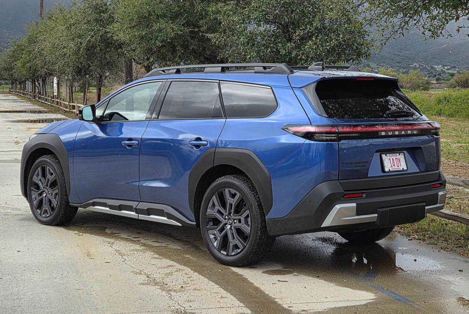
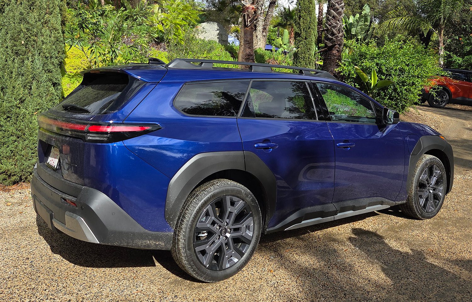
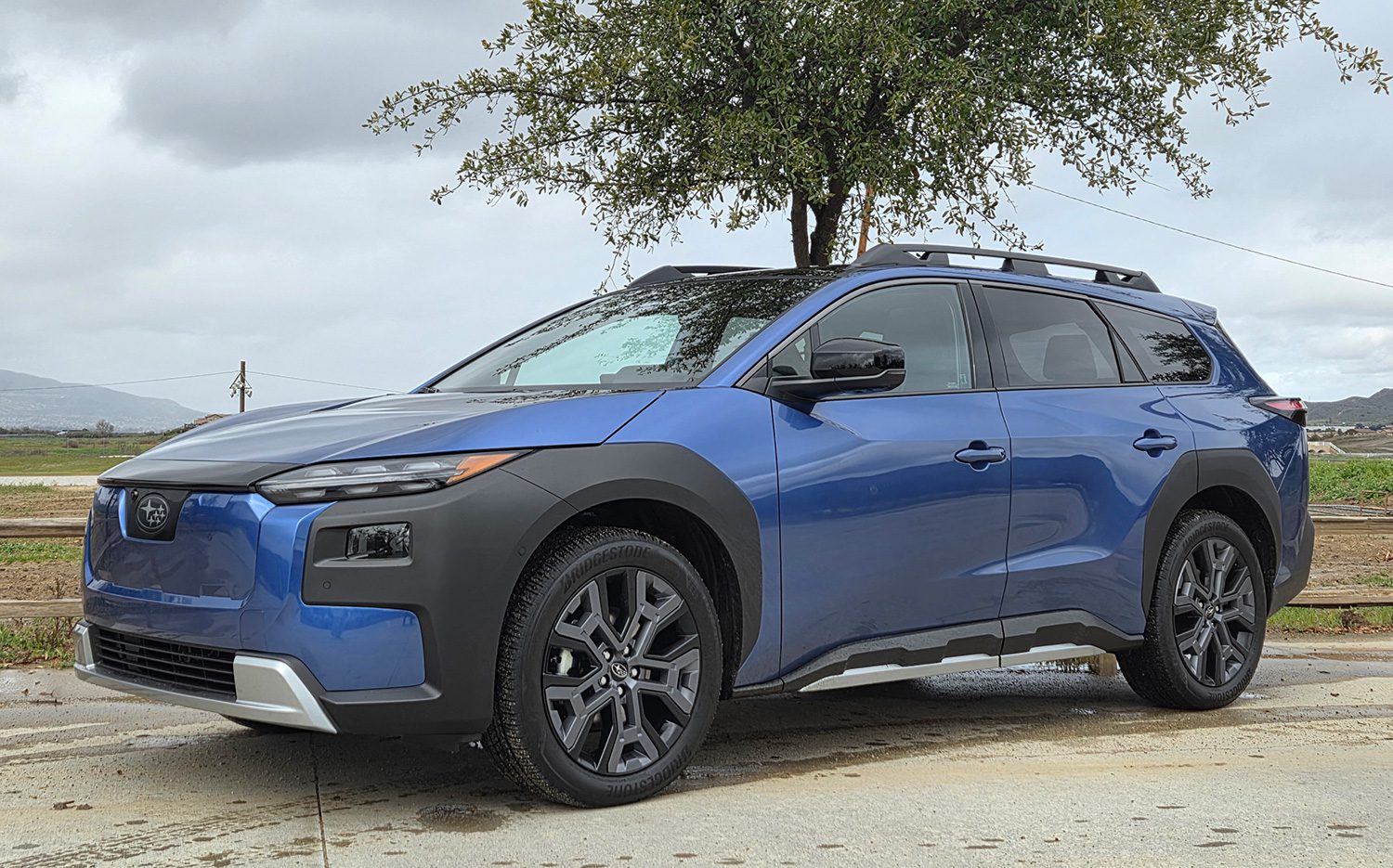
The most Subaru of all the brand’s EVs is visually identifiable, competent off-road and on—and lighter than competitors.
“When we showed them the side view, without any badges, and asked them what brand it was, everyone said, ‘It’s a Subaru!’,” said Garrick Goh. He’s the car line planning manager for the 2026 Subaru Trailseeker, the third of Subaru’s three battery-electric models. It’ll go on sale within several weeks as, he said, “the most Subaru of all our EVs.”
Why is the Trailseeker so identifiable as a Subaru? It’s a classic wagon shape, and it has roof rails for adding luggage bins, or ski, snowboard, or surfboard carriers. It’s the only electric SUV with ladder-type roof rails, for all the many Thule and other accessories the brand’s outdoorsy owners add to pursue their “active lifestyles”. It’s even got a standard rear wiper (terrible for aerodynamic drag) and standard headlamp washers.
In design clinics, shoppers said the new EV looked “spacious and versatile,” “rugged and adventurous,” with an “outdoorsy spirit.” But it still looked like “it could handle different terrains while still being comfortable.” Which is to say, the survey group described exactly the traits for which the mainstay Outback is known. In the same year that the Outback grew several inches taller, much squarer, and more SUV-like—causing great agita among auto reporters, if not necessarily actual Subaru shoppers—the new EV and its recognizable shape might just be the car existing Outback owners gravitate toward when it’s time for the next one.
A Solterra wagon, effectively
Jointly developed with Toyota, like all of Subaru’s EVs, the Trailseeker is effectively a wagon version of the Solterra that’s been on sale since 2023. In fact, it’s identical to that hatchback from the rear doors forward. Pretty much only the roofline, the rear windows, and the tailgate had to be changed. But while Toyota calls its version the bZ Woodland, simply an added version of its bZ (which is the Solterra with a different badge), Subaru chose to give its EV wagon a new model name and a sharply separate identity. Given its appearance, that’s probably smart.
Subaru’s designers developed the Trailseeker/Woodland wagon on the Solterra base car, and it’s built in the company’s Gunma Yajima plant. That makes it the first EV Subaru has built, at least since it sold a few hundred electric minicars 20 years ago, in contrast to the Solterra itself. That model is assembled alongside its bZ sibling at Toyota’s Motomachi plant in Japan.
The Trailseeker uses the same 74.7-kilowatt-hour battery pack as not only the Solterra but also its smaller 2026 Subaru Uncharted hatchback sibling, which will join the larger wagon-esque EV in showrooms at roughly the same time. The smaller car starts at $36,500 including delivery, though only if you get the front-wheel-drive model with an EPA-rated range of 307 miles; it’s the first FWD-only model Subaru has sold in the US in three decades.
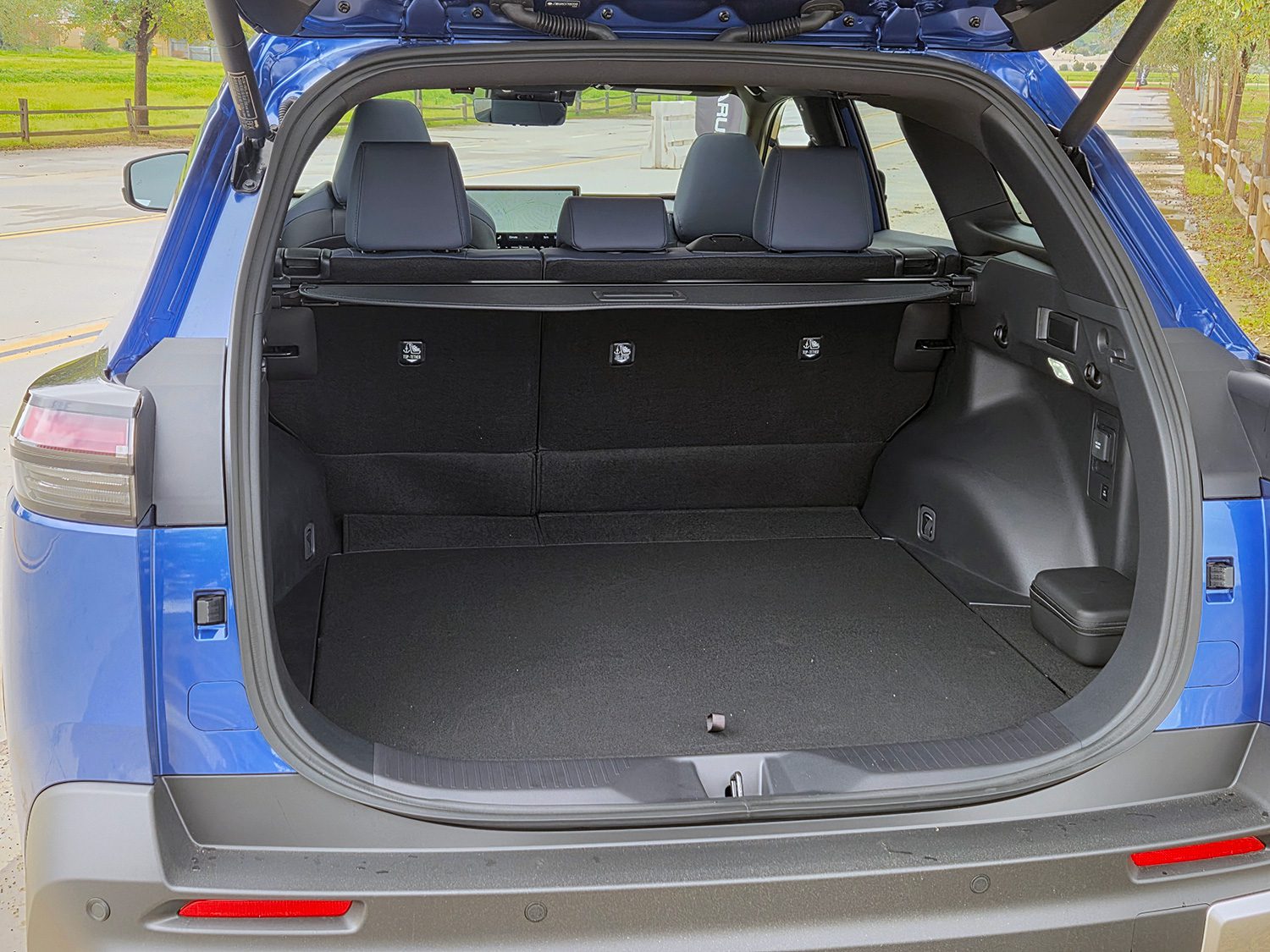
All Trailseekers have all-wheel drive standard, via a pair of electric motors with a combined power rating of 280 kilowatts (375 horsepower). Subaru quotes a 0-to-60-mph acceleration time of 4.4 seconds in Power mode; there are also Normal and Eco modes. Other stats of interest: The Trailseeker is rated for up to 3,500 pounds of towing, has a best-in-class 8.5 inches of ground clearance, and 31.3 cubic feet of cargo capacity with the rear seat folded up. In its presentation, Subaru included photos of golden retrievers and a great deal of data on how likely its owners were to have pets, especially dogs.
On the road: competent, unremarkable
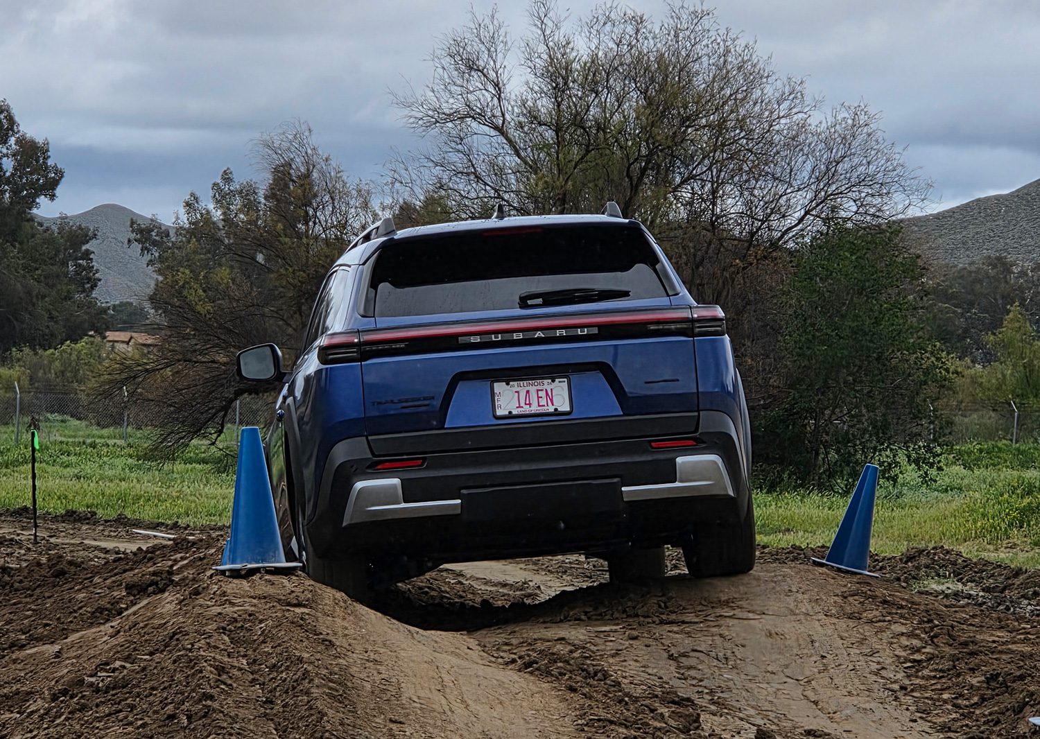
We drove a pre-production top-of-the-line Trailseeker Touring among the hills and freeways of Orange County, California. Subaru’s plans for elaborate off-road activities were scuppered by torrential rains, but a temporary off-road course with enough dips and rises let us lift one or two wheels off the ground, even at 8.5 inches of ground clearance.
The off-road X-Mode drive setting handled hills, ruts, gullies, and wheel-up situations with aplomb, as essentially any AWD Subaru does. That’s the brand’s special sauce, and it sometimes out-climbs and out-maneuvers far pricier, larger, and more luxurious SUVs with extroverted designs that scream “off road”. We’ll be curious to see whether Subaru will add a Trailseeker Wilderness model, with even more ground clearance and exaggerated off-road trim.
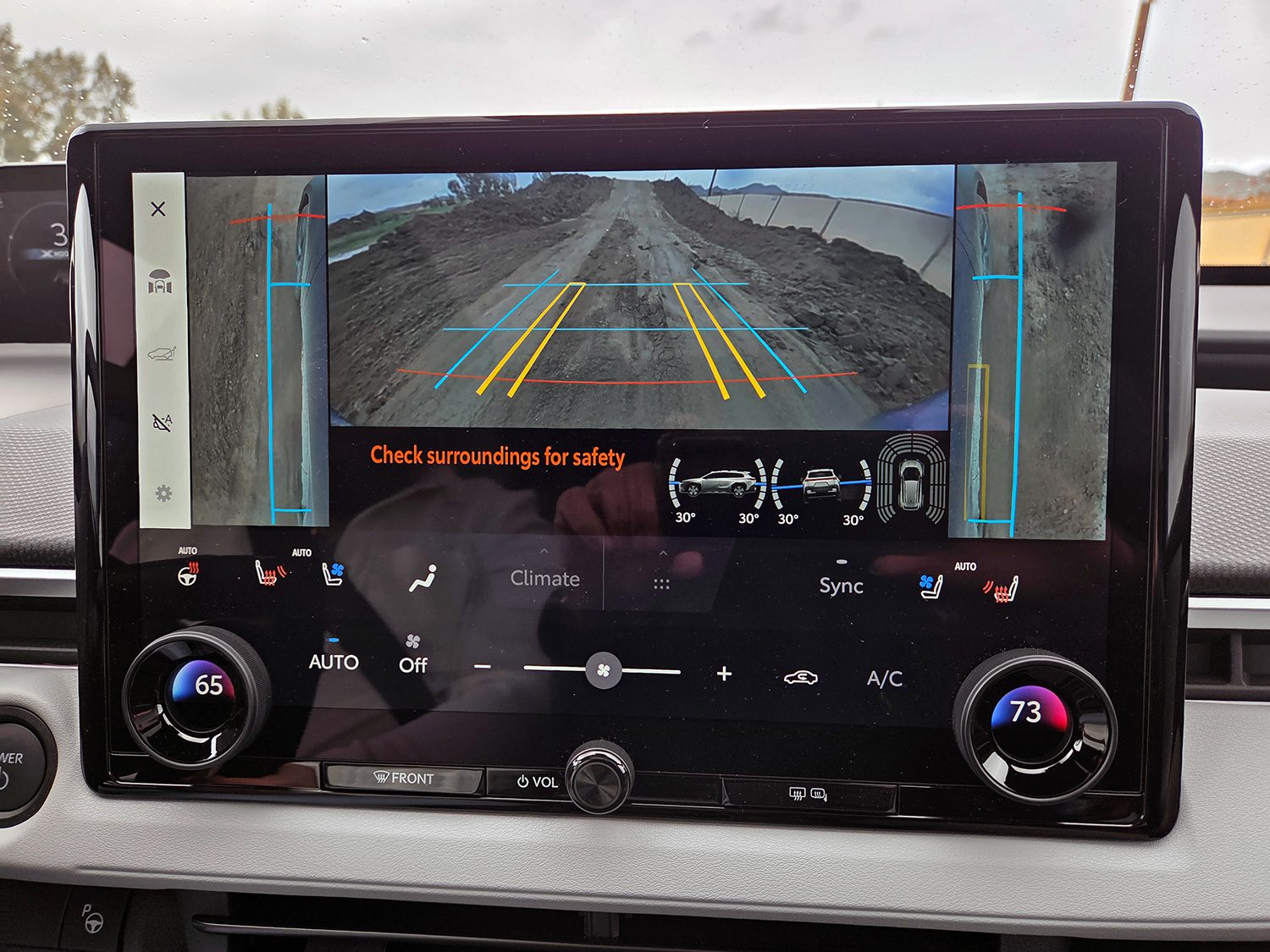
As with the smaller Uncharted, the wagon’s X-Mode Multi-Terrain monitor view offered a front-facing camera. That proved incredibly useful in seeing past steep downhill breakover angles atop the muddy hillocks of the course. But in both cars, that view disappeared above 6 mph—apparently a Toyota safety measure—meaning we had to stop and then go through the multiple steps off re-selecting it before the next hill. Annoying, and borderline unsafe.
Once we returned to pavement, the Trailseeker proved itself predictable, competent, and quiet. As an EV, of course, it lacked the characteristic Subaru thrum from the horizontally opposed four-cylinder engine that’s been the brand’s defining feature, along with AWD, since the 1970s. But frontal visibility was good over a relatively low cowl, and the upright shape made over-the-shoulder visibility better than the Solterra hatch with its thick, angled roof pillars.
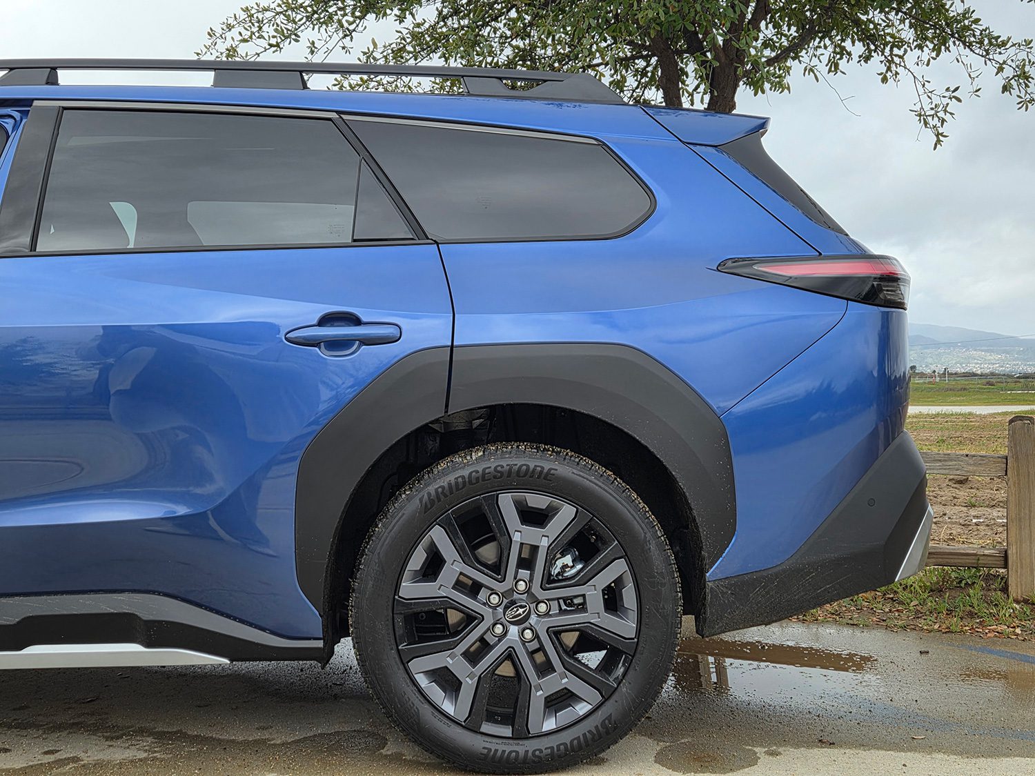
The regenerative braking is far from the strongest in the class. It was learnable, but we would each have liked the option of a stronger setting. Arguably Toyota’s powertrain engineers decided battery life would benefit from limiting regen, just as they limited power delivery. Steering feel is predictable, if numb. And the tires had decently tall sidewalls, which kept the Trailseeker’s ride smoother than the “rubber-band tires” with low sidewalls on big wheels found on competitors’ top-trim models.
Lighter than competitors
One crucial data point: At just below 4,400 pounds, the Trailseeker Premium is more than 300 pounds lighter than the next-lightest competitor. The weight difference ranges all the way up to the Honda Prologue Touring AWD, which is more than 800 pounds heavier—and has a larger battery as a result. The joint efforts of Toyota and Subaru engineers have created a lighter EV, one that doesn’t have the neck-snapping acceleration of some competitors, that manages to eke out acceptable range from a somewhat smaller battery—which lowers costs—despite the aerodynamic penalties of the roof rails, rear wiper, and high ground clearance.
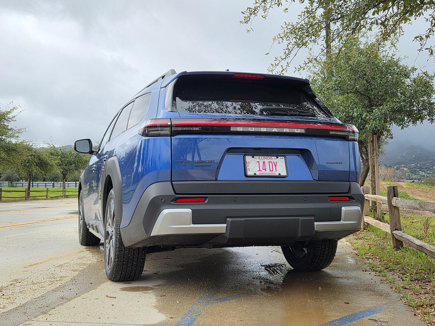
The design is a mix of Toyota and Subaru cues. The slab-sided wagon shape is all Subaru, though there’s no Subaru star logo on the tailgate. Instead, individual letters spell out Subaru, with lights behind them illuminating the brand at night on top trims.
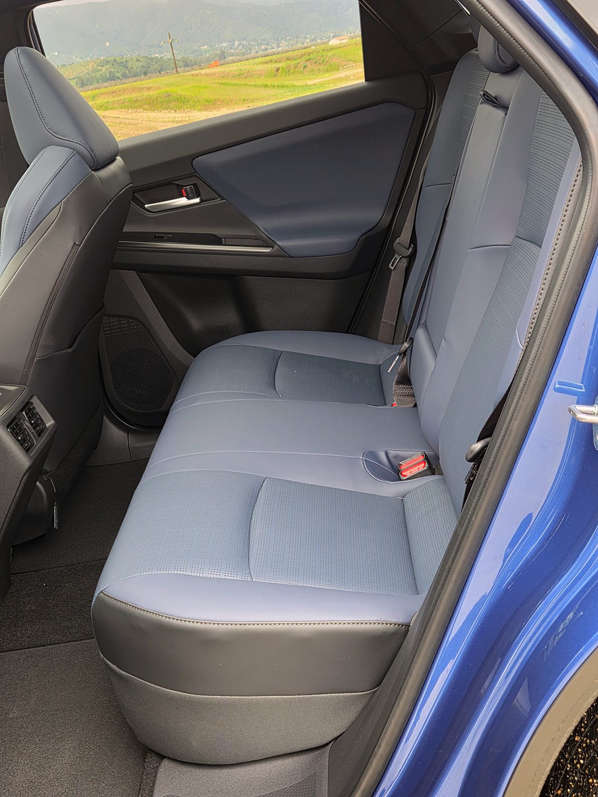
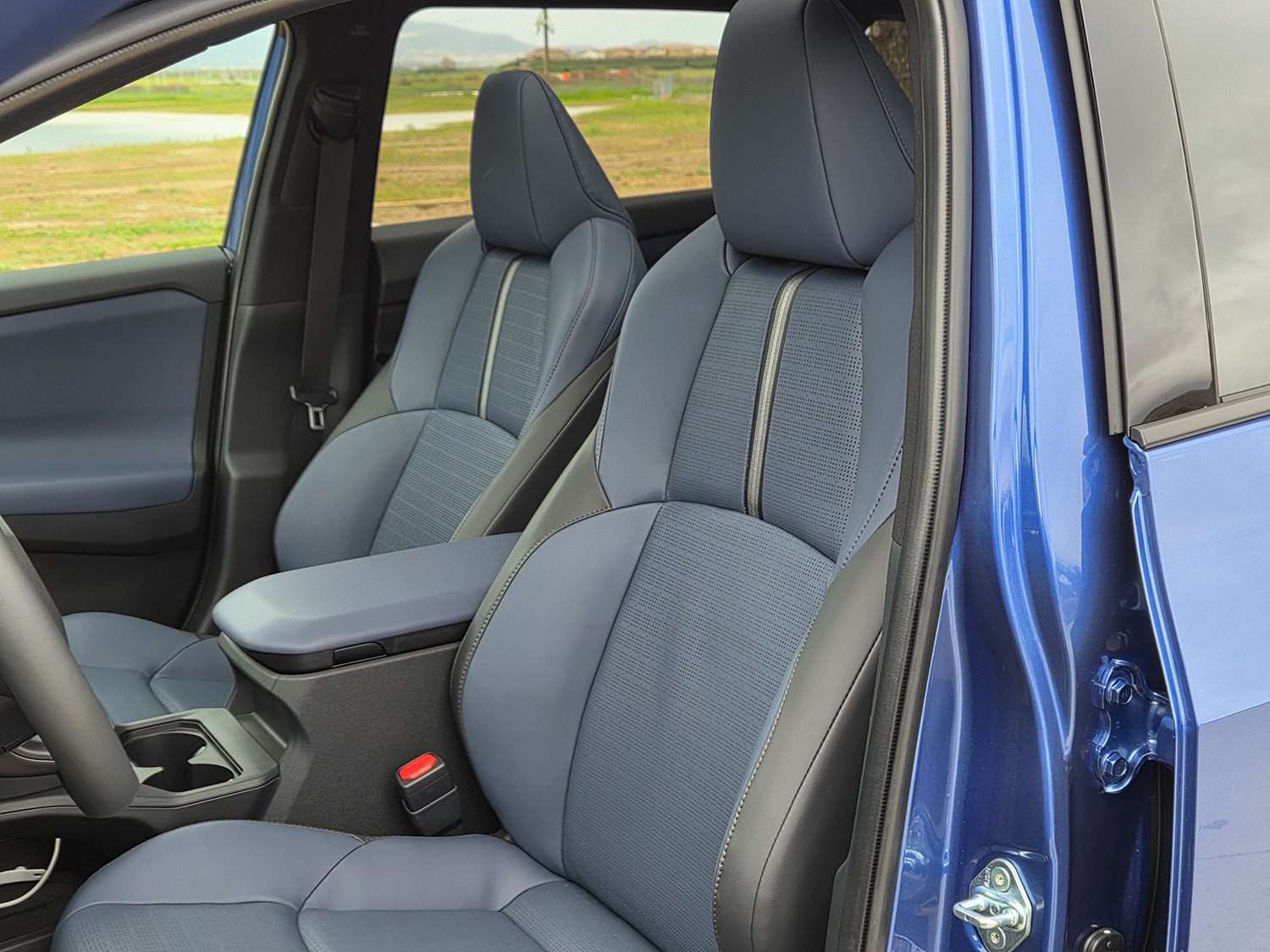
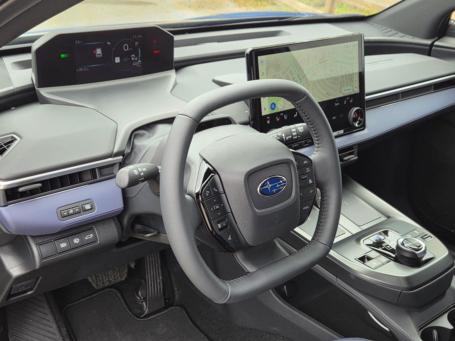
Inside, the available two-tone blue leather upholstery inserts were a pleasant relief from the usual all-black cabin. Grey two-tone is also available. Much of the rest of the interior was made up of hard plastic surfaces. Instruments are all Toyota, with a digital gauge cluster at the base of the windshield and a vertical center touchscreen. To ensure the cluster remains visible, the steering wheel is a rectangle with rounded corners—a different brand calls it a “squircle”—which we found easy to adapt to. A startling annoyance was the lack of a glove box; why?
The Trailseeker is fitted with a North American Charging Standard (NACS) port, aka “the Tesla port,” and under ideal circumstances can charge from 10 to 80 percent in as little as 28 minutes on a DC fast charger capable of delivering a consistent 150-kW rate. And it can charge at Level 3 and Level 4 Tesla Supercharger stations, now roughly 25,000 of Tesla’s total of 36,000 chargers. Owners in Subaru’s stronghold colder and snowy climes will appreciate the built-in battery preconditioning. The car comes standard with both DC and AC adapters for CCS and J-1772 charging stations, respectively.
Subaru’s EV-curious owners
More than one-third of Subaru’s existing, very loyal owners would consider an EV for their next vehicle, according to its data. That’s the third highest level of all non-Tesla brands, trailing only Volkswagen (which has sold EVs in the U.
S since 2021) and Mazda (which has no EVs at all).
Subaru says the new model competes—at least on specs—with the Chevrolet Blazer EV, Ford Mustang Mach-E Rally, Honda Prologue AWD Touring, Hyundai Ioniq 5 XRT, Kia EV6 Long Range AWD with 19-inch wheels, and the Volkswagen ID.4 AWD. It carefully constructed its comparisons to ensure all those vehicles had AWD and the most off-road-inflected trim levels. It did not, however, include the Tesla Model Y in the comparison set. That aging model is by far the sales leader across compact premium electric SUVs, though its U. (and global) sales have declined for two years as newer, fresher entries hit the market.
The Trailseeker starts at $41,445 for the base Premium model, rated at 281 miles, while the better-equipped Limited and Touring trims ($45,445 and $48,005 respectively) get a 274-mile range. (All prices include the mandatory $1,450 destination fee; ignoring that lets Subaru claim a sticker of “less than $40,000” for the entry version). Execs suggested Trailseekers might start to arrive at Subaru dealerships in April.
Subaru provided airfare, lodging, and meals to enable Charged to bring you this first-person drive report.
KULR Technology Group and Texas-based drone maker Hylio have signed a joint development collaboration to design, prototype, qualify, and manufacture battery systems in Texas for Hylio’s unmanned agricultural drones.
The companies said the goal is to produce NDAA-compliant (National Defense Authorization Act) battery packs for integration into Hylio’s UAS platforms, with an emphasis on US-based supply chains and “mission-critical” architectures suited to agricultural and defense-adjacent applications. KULR said engineering, integration, and manufacturing activities are expected to be centered in Texas.
KULR also cited growing regulatory scrutiny and federal procurement standards as drivers of demand for domestically manufactured, NDAA-compliant components. The release pointed to a Research and Markets forecast projecting the global agricultural drone market will grow from $4.08 billion in 2026 to $8.65 billion by 2032.
“Domestic, NDAA-compliant energy storage is becoming a foundational requirement for advanced unmanned and defense-adjacent systems,” said KULR CEO Michael Mo. Hylio CEO Arthur Erickson said the collaboration is intended to strengthen Hylio’s supply chain and “enhance performance capabilities.”
Electromobility is rapidly expanding into heavy‑duty transport, creating a need for charging technologies that can handle large battery systems. The Megawatt Charging System (MCS) addresses this challenge with a new international standard for high‑power DC charging of commercial vehicles and other large electric platforms.
As with passenger‑car charging, reliable communication between the vehicle and the charging station is essential. MCS uses ISO 15118‑20 and 10BASE‑T1S automotive Ethernet to enable this interaction, both supported by our Smart Charging Solution.
In this webinar at our March Virtual Conference on EV Engineering, presented by dSPACE, we demonstrate a complete high‑power charging process and show how the communication protocol and its connection to the charging application can be tested efficiently. The accompanying slides outline the technical background, test setup, and key challenges of megawatt charging.
Broadcast live from March 9 to 12, 2026, the conference content will encompass the entire EV engineering supply chain and ecosystem, including motor and power electronics design and manufacturing, cell development, battery systems, testing, powertrains, thermal management, circuit protection, wire and cable, EMI/EMC and more.